How to Apply PBR Textures in Blender
The purpose of this tutorial is to teach 3D artists how to manually apply physically based rendering (PBR) textures in Blender (3D modeling software).Model
Before applying any textures, a 3D model is required. In this tutorial, the following car model is used for demonstration.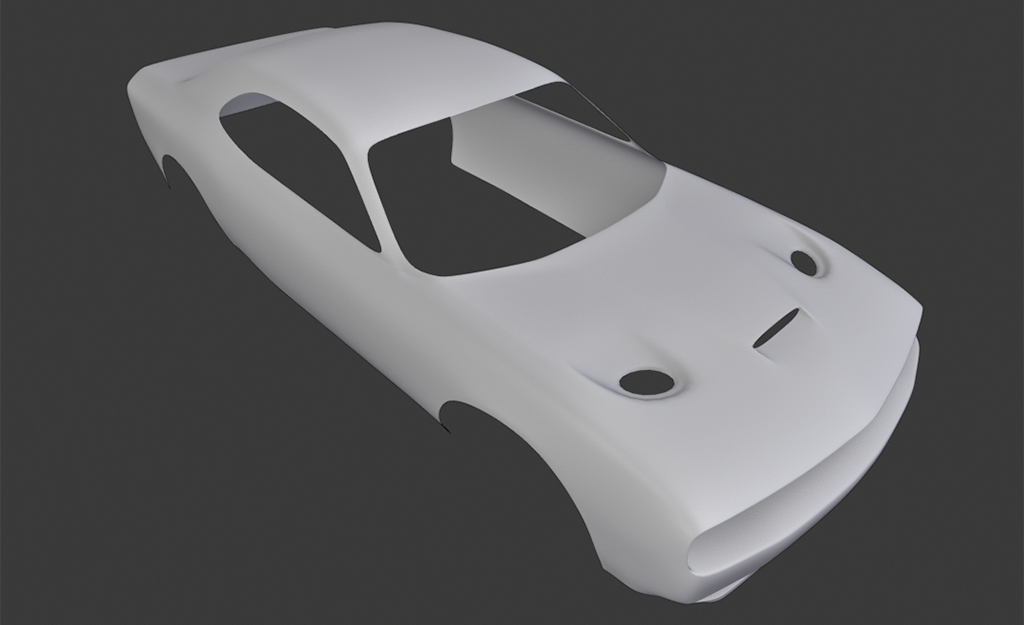
UV Unwrap
UV maps of all 3D models MUST be unwrapped first before applying PBR textures.To unwrap a 3D model,
- Open the UV editor.
- Select the model and press the <Tab> key to enter Blender's Edit mode.
- Press A key to select all vertices.
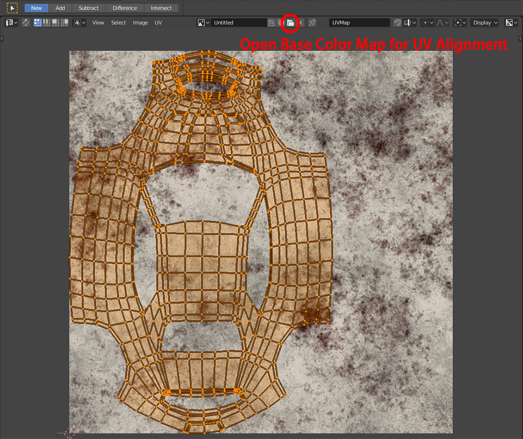
- Press U key and select the desired unwrapping method such as Unwrap, Smart UV Projection, Box Projection etc. It depends on the shape of the mesh.
- Press the red circle button indicated in the following diagram and open the Base Color Map downloaded from TextureCan.com.
This step is optional, but it can ease the texture alignment.
Metallic Workflow and Principled BSDF Shader
All texture maps offered by TextureCan.com follow metalness workflow which is 100% PBR safe.In metalness workflow, the following maps are used for rendering:
- Base Color Map
- Normal Map
- Roughness Map
- Metallic Map
- Diffuse Map
- Normal Map
- Glossines Map
- Specular Map
The metallic values of non-metallic (aka. dielectric) materials can be set to 0.
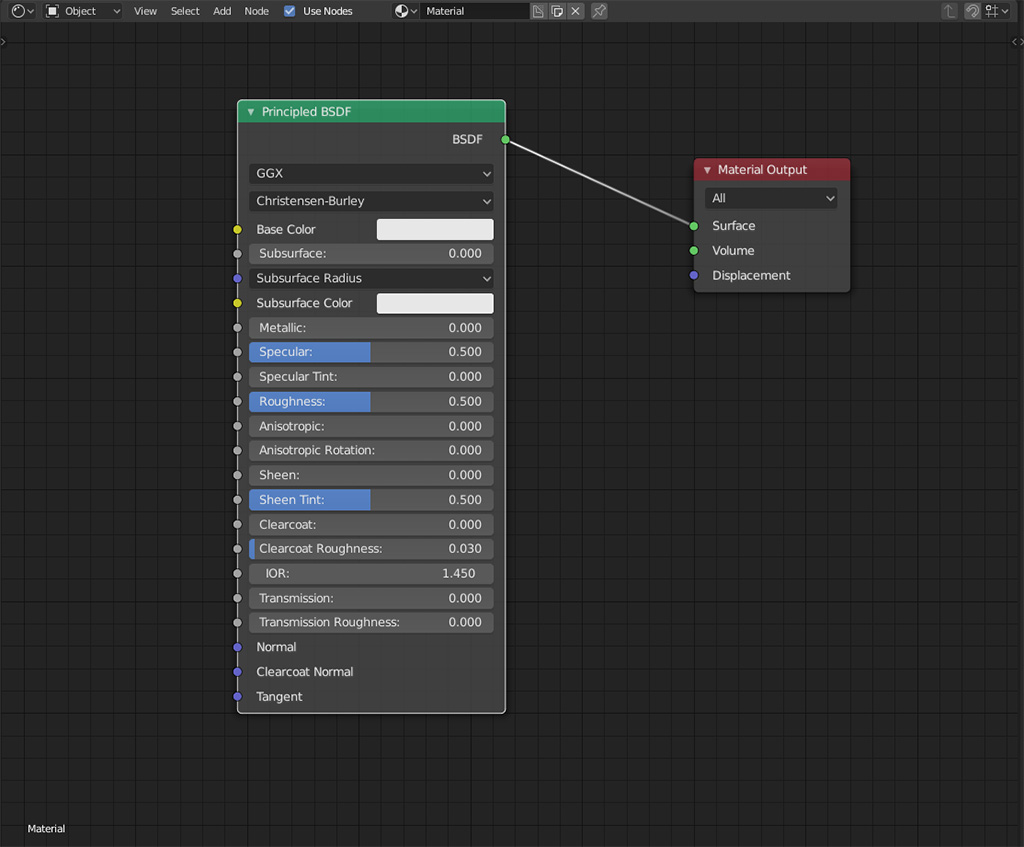
While the model is still being selected, the UV editor's panel can be switched to the Shader Editor.
Click the Use Nodes checkbox if it is not checked.
By default, the latest Blender version use PBR or metalness workflow as its rendered result which is more accurate than specular workflow's.
Principled BSDF is a PBR shader in Blender. It takes all metalness workflow maps.
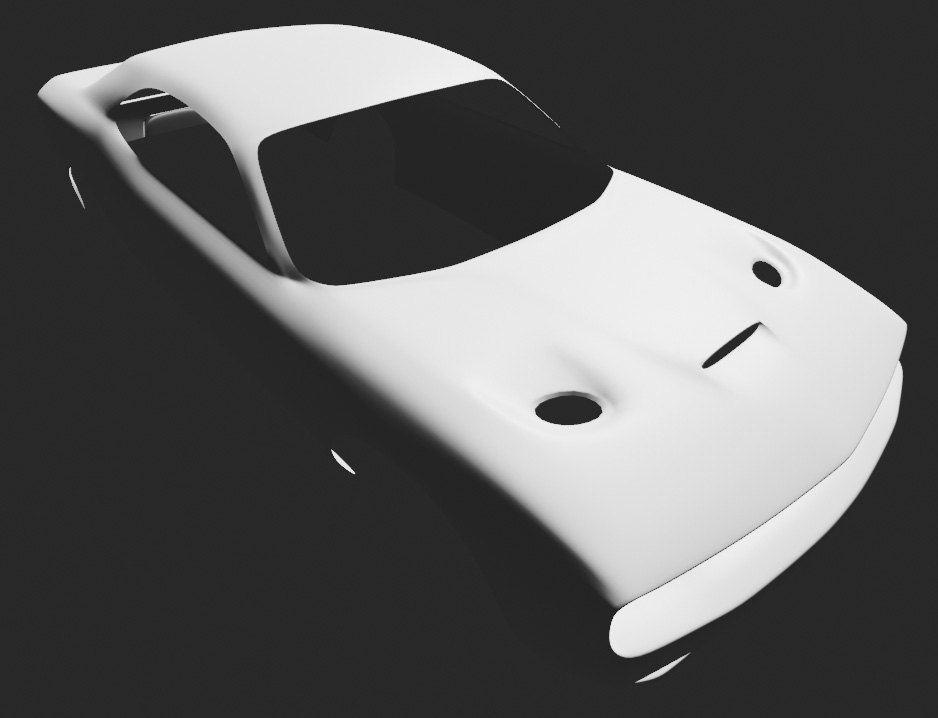
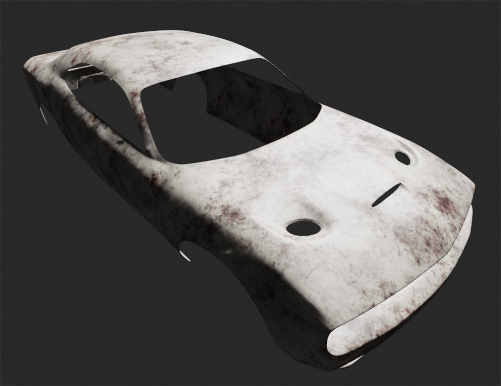
If the car model is rendered now, it will look like:
Base Color
Base color map is responsible for defining colors of textures. Shadows and highlights are taken off from the base color map, so it is a purely albedo map.All texture maps can be imported into Blender by Image Texture nodes.
In this tutorial, "Rusty Metal Texture with Bumpy Surface (Metal 0004)" is used.
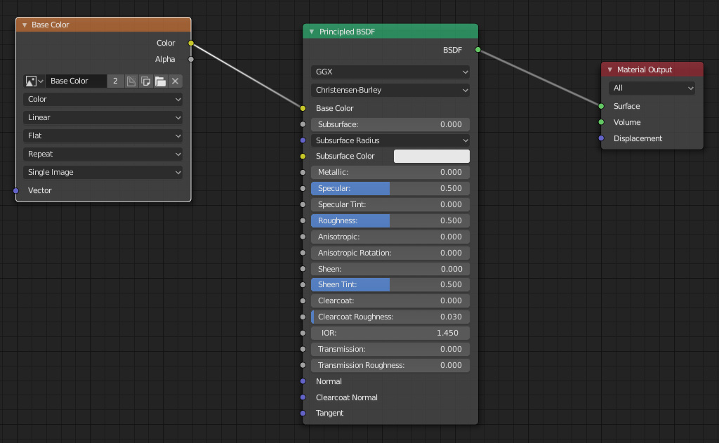
The "Base Color" image texture node should be connected to the Base Color input of the Principled BSDF node.
The color space should be set to "sRGB" (default value) or "Color" for old version.
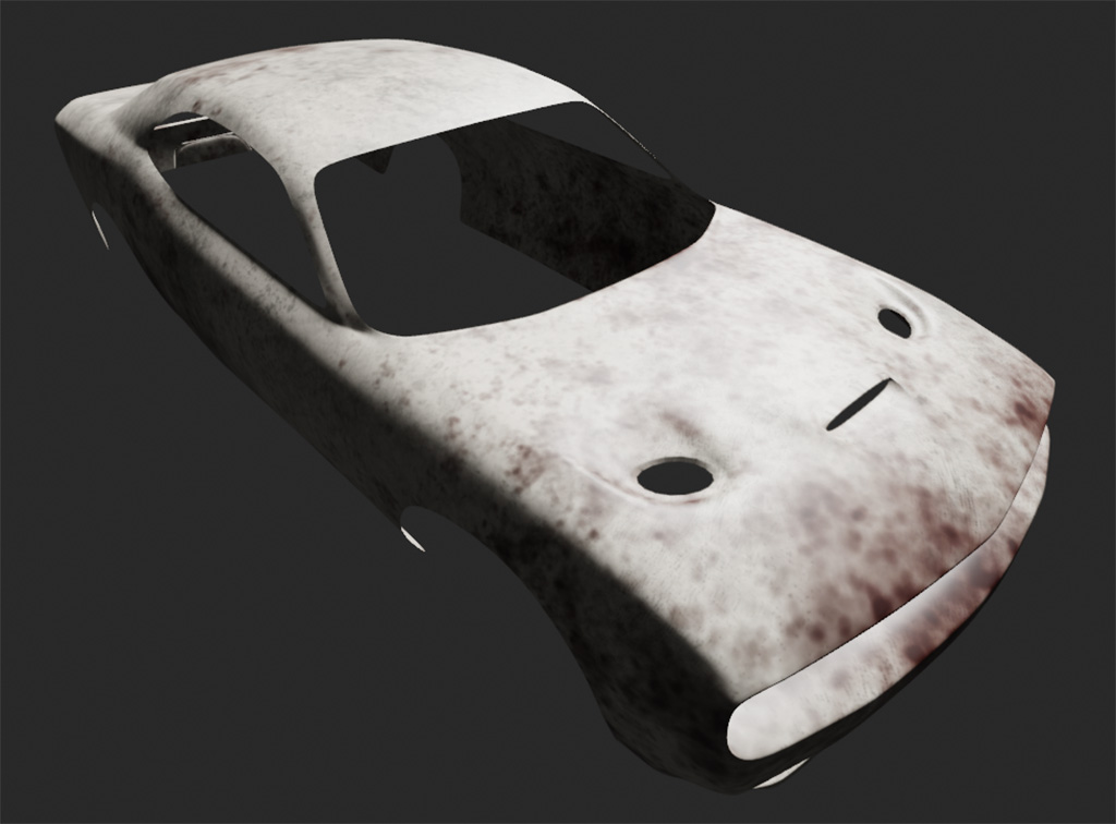
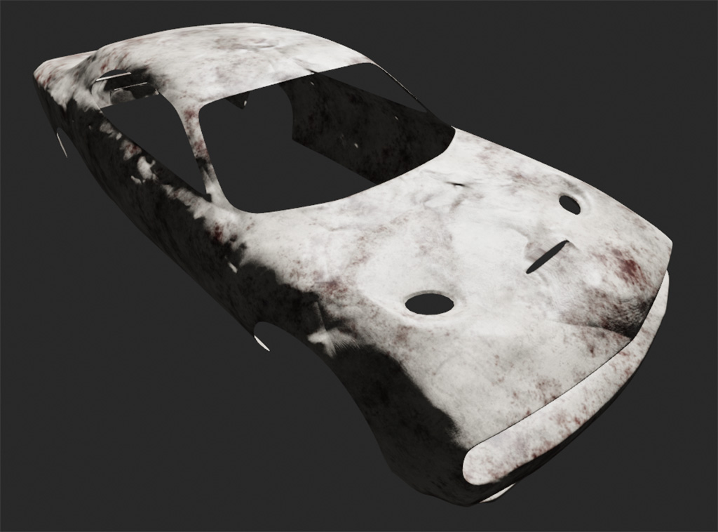
The car model becomes:
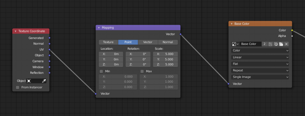
3D model sizes can range from a few centimeters to a few meters. Usually, the scale of the texture should be adjusted.
To scale all the texture maps, Texture Coordinate node and the Mapping node are used.
In this case, the scale of the mapping is changed from 1 to 5 for x, y and z directions.
The Mapping node should be connected to all image texture nodes, otherwise, the alignment of other maps will be wrong.
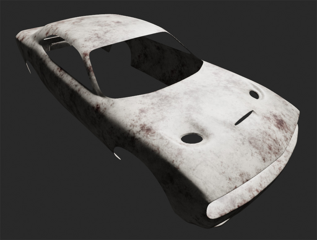
Here is the rendered result after scaling the Base Color texture map.
Normal
Besides Base Color map, Normal map also gives dramatic changes to a 3D model.It defines the directions each surface is facing. Besides directions, it also stores the height or strength of each face, so it can create height variance and affect shadows and highlights.
Again, the normal map is brought into Blender via an Image Texture node. Of course, the image file should be set to the normal map.
Please note that a Normal Map node is used to convert an image texture into a normal and the color space is set to "Non-Color"
Friendly reminder: Please remember to connect the Mapping node to this newly added Normal map.
With Base Color and Normal being applied, the rendered car becomes:
It depends on the taste and need of 3D artists. A strong normal effect can be achived by increasing the Strength value of the Normal Map node.
Here is the result after changing the normal strength to 5:
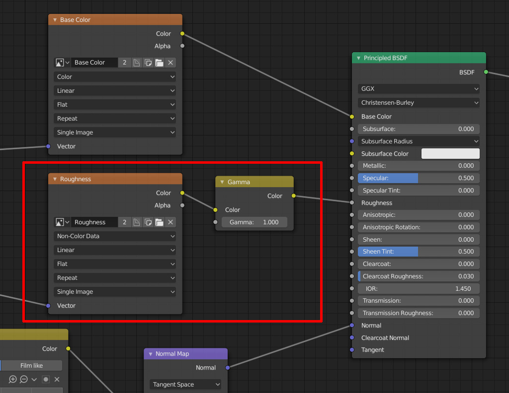
Roughness
As the name "roughness" implies, it defines how rough a surface is.Same as Normal Map, the color space of the Image Texture must be set to "Non-Color".
Sometimes, 3D artists want to adjust the pre-set roughness.
It can be done by inserting a Gamma node between the Image Texture node and the Principled BSDF node.
If the Gamma value is reduced, the roughness will be increased and vice versa.
Then the Gamma node is linked to the Roughness input of the Principled BSDF node.
Do you remember to connect the Mapping node to this roughness map?
With the roughness, the car model becomes:
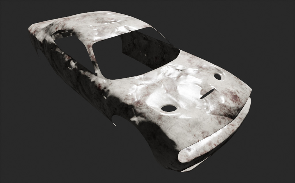
The roughness map gives the rendered model a substantial change.
Metallic
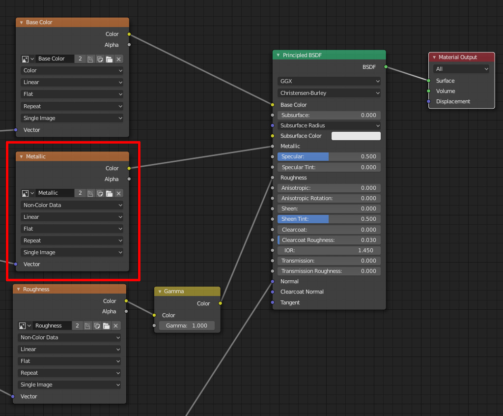
Metallic map defines which parts are metallic and which parts are not. Theoretically, materials should either be metallic or non-metallic.It is very straight forward to apply a metallic map. A single Image Texture map will do the job. Be reminded that the color space should be "Non-Color".
The Image Texture should be plugged into the metallic input of the Principled BSDF.
If the material is non-metallic, the metallic map will NOT be provided and the metallic value should be set to 0.
Do not forget to plug the Mapping node into the vector input of the metallic node.
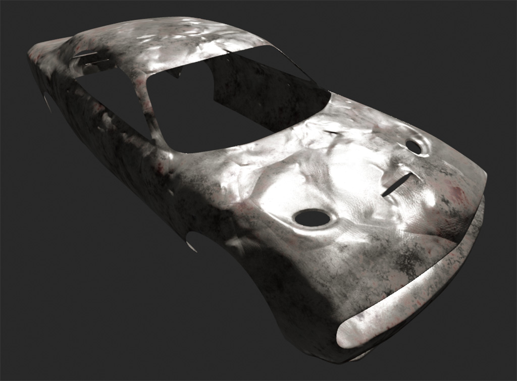
The plastic car has been changed into a metallic car now.
Displacement Map or Height Map
Displacement map is also known as Height Map.A displacement or height map is used to displace the actual geometry of a mesh while a normal map is used to define fine details of the micro-surface.
Displacement maps can cause larger degree of deformation. It usually defines macroscopic levels of displacement.
Normal maps do not need any subdivided meshes (it just fakes the lighting) to work while displacement or height maps require subdivided meshes.
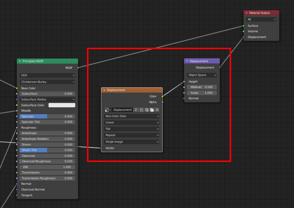
Firstly, link the Mapping node to the Image Texture node.
Secondly, load the height map and set the color space to "Non-Color".
Then the Color output of the Image Texture node should be connected to the Height input of the Displacement node.
Lastly, the Displacement node is plugged into the Displacement input of the Material Output.
Yes, it is connected to the Material Output instead of the Principled BSDF node.
There are 2 more steps.
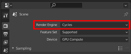
Currently, only "Cycles" supports the height / displacement map. The Render Engine should be set to Cycles (Default: Eevee).
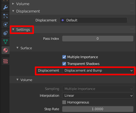
Next, go to "Material Properties" panel, scroll down to the "Settings". After expanding it, please change the Displacement value from "Bump Only" to "Displacement and Bump".
What will the model look after applying the displacement map?
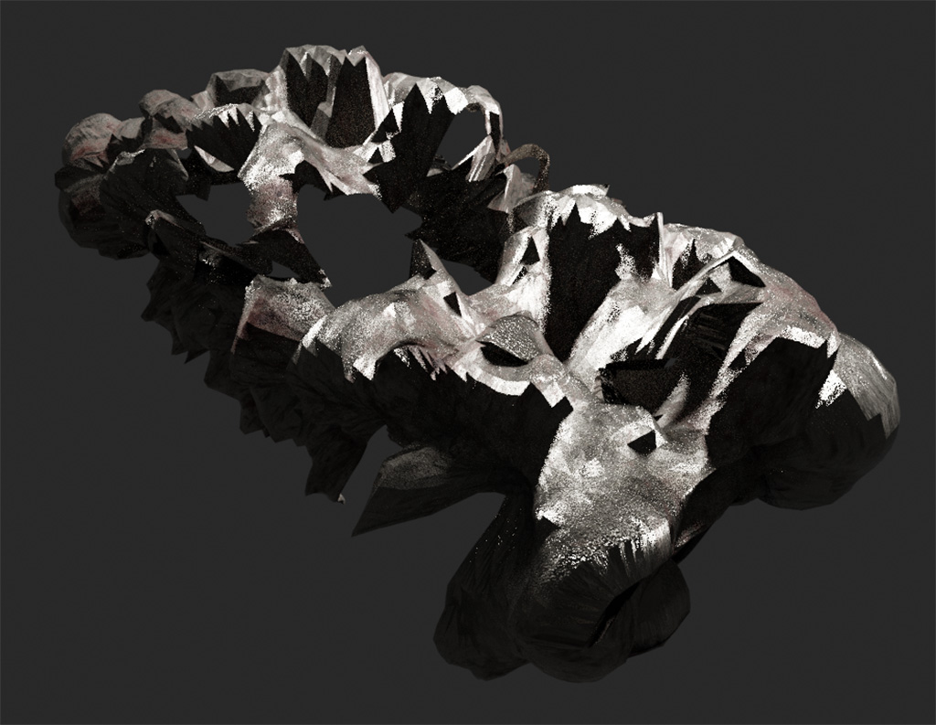
The car model is totally destoryed by excessive displacement.
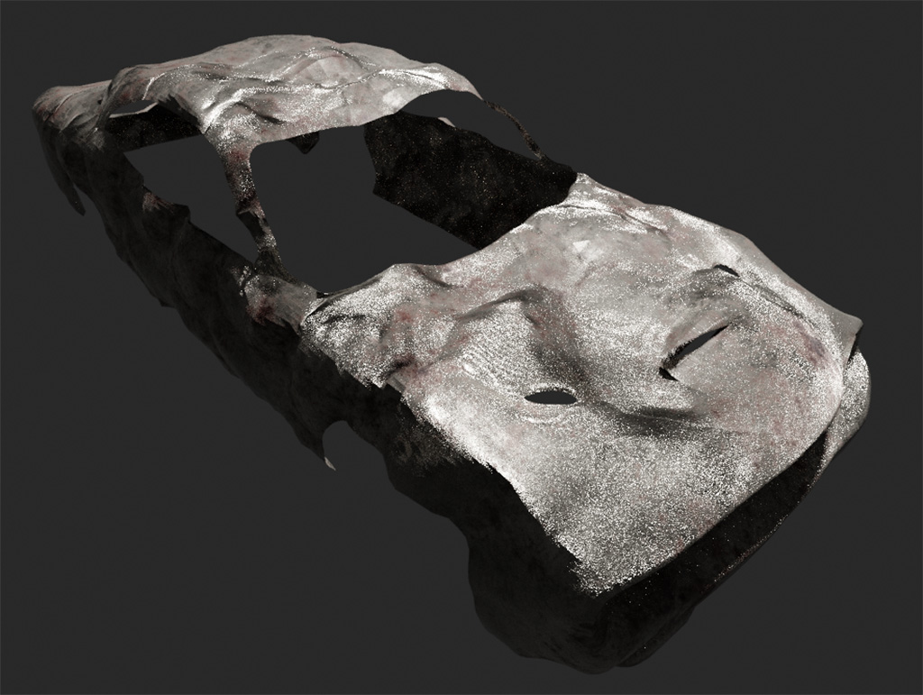
If the scale of the Displacement node is changed from 1 to 0.15, it becomes:
Here is the result if the scale is set to 0.01:
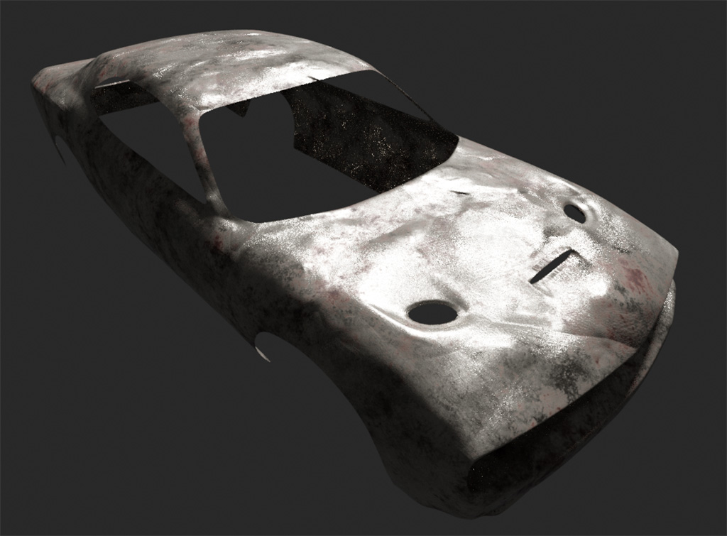
Most of the time, a gentle displacement is enough.
The strength of the Displacement node is kept at 0.01 in this tutorial.
Ambient Occlusion
Ambient occlusion (AO) is used to artifically enhance shadows of rendered models. An excellent render can still be achieved without applying an ambient occlusion map in Blender.In fact, Principled BSDF does not have a dedicated input for AO.
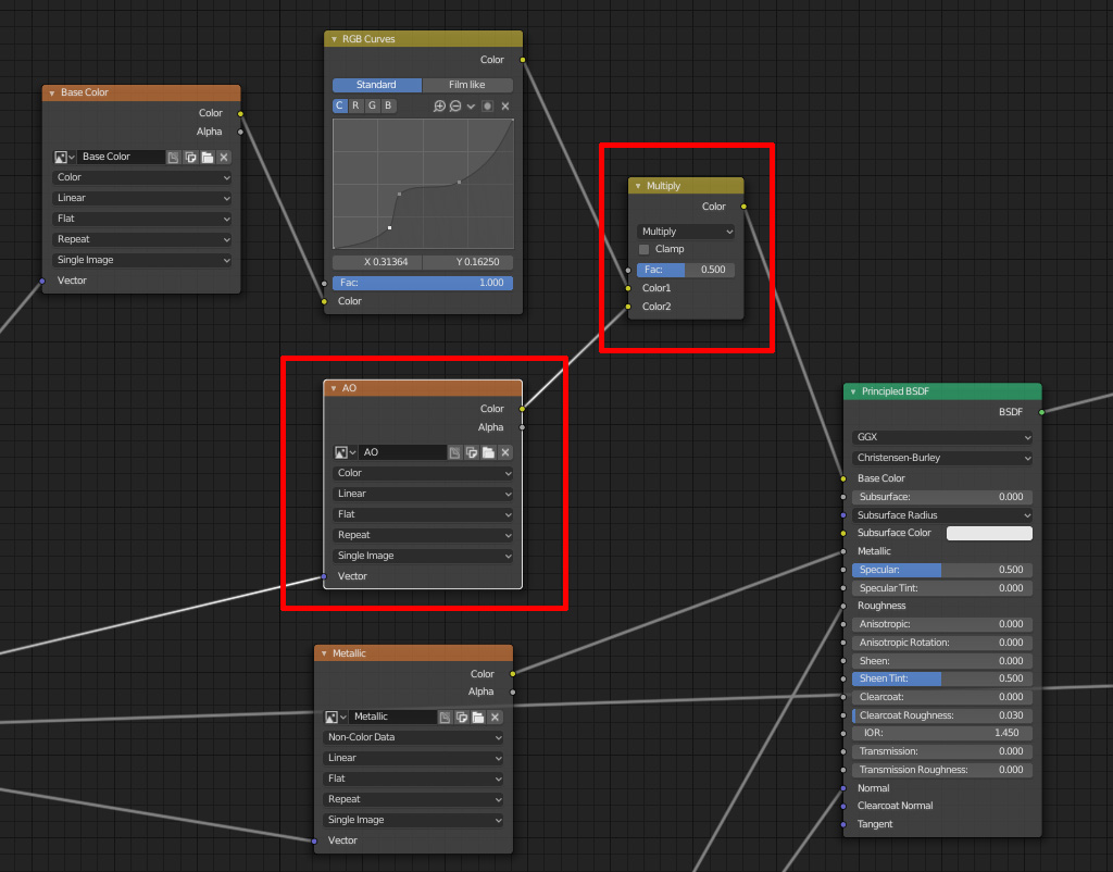
To integrate ambient occlusion, a MixRGB node can be used and the blending mode should be set to "Multiply".
The strength of the ambient occlusion can be adjusted by the "Fac" of the MixRGB node. Bear in mind the effect is very subtle.
Of course, the Mapping node (if any) should also be plugged into the AO Image Texture node.
Base Color Tweak
Almost all the maps have been applied, 3D artists can tweak different values of the maps to achieve desired result now.For example, the base color can be exaggerated by manipulating the RGB curve.
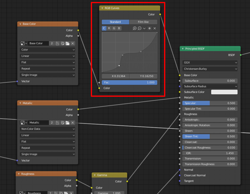
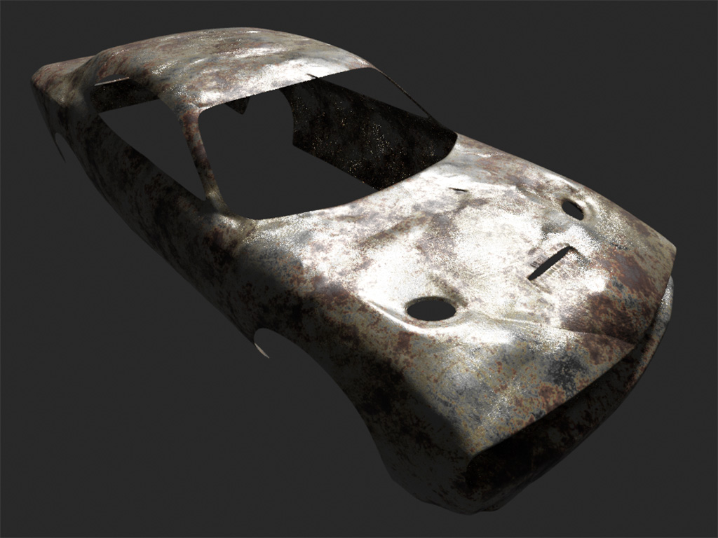
The rendered model looks more attractive after the base color is being tweaked.
That's all for the tutorial.
Thank you for your reading!
Happy rendering!